Game Boy Color Style Rendering Pipeline in Blender / Malt
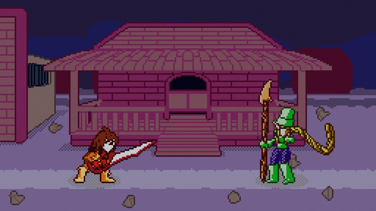
Oh look! A rendering article! Do I still do that? If you’re looking just at this site, I kinda do, but I’ve been mostly working on Castagne for the past few months. If you followed what I posted, you might have seen some screenshots of a small game I’m making called Molten Winds, which features a Game Boy Color inspired artstyle!
You may be asking “Panthavma, you’re a 3D guy. Why are you drawing sprites?”. I don’t! At this point, it makes a lot more sense for me to apply 3D for almost all assets, and these are a fantastic example of usecase. Molten Winds has been started because I needed a smaller scale project to push Castagne and its 2D graphics component. Because of that I wanted something simple, pixel art with a low resolution, and figured I would use the style of the GBC, since I like it! I especially like the look of Oracle of Ages/Seasons. Since I want to knock those sprites out quickly, I need the support of 3D rendering to make my frames and adjustments painless.
So I went and made this shader and workflow on instinct! It’s not very hard, especially since as I’m not running in a game engine I don’t have a lot of limitations. It’s a very simple two-pass shader (but lots of buffers), but does have an effect on people, as I’ve seen during the panel I participated in during the Niche Fighter Fête! In this article we will look at:
- What exactly is the style we want to make
- How do we setup blender to handle that
- How the shader actually works
- How to make assets working with it
- How to export to game engines
Game Boy Color limits and liberties
Something to think about is if you want to strictly reproduce a style, or if you’ld rather just evoke the style. In my case, I’m going for the latter. Standards evolve over time, and sometimes the same thing may look a lot worse now than it did back then, even before you factor in the fact that we don’t use the same screens at all. In addition to that, faithfully reproducing the style would put a lot of limits I don’t want to work with.
So let’s start with some specs of the GBC!
- Resolution: The GBC’s resolution is
160x144, and the screen is44x40mm. Since I’m making a game for modern systems, I’ll use a resolution of256x144! This keeps the total pixel density similar, which helps to stay closer to the style. I however keep my options open for the game itself, for some specific elements like text to be displayed at double resolution if needed. I’m also not simulating the screen itself for now, since that’s outside of sprites and may be distracting on modern LCDs. - Sprites: The GBC has an internal limit for sprites to be
8x8or8x16, restricting a lot of possibilities. Developers back then would often use several sprites for one character to compensate, which is also logical for a fighting game, so I’ll be just evoking this aspect by separating my models into “parts”. There are also limits like “40 sprites maximum” and “10 sprites per line maximum”, which I completely ignore. - Colors: The GBC’s screen can display 32768 colors (15-bit), but the hardware could only handle 16 color palettes of 4 colors each. And out of those, only 8 were for sprites, and one of those colors must be transparent, so in total you have 56 colors maximum (without special tricks), a number probably higher than in reality since some palettes will share colors like black. This is also a limit on how you make sprites, since you have to keep the same palette in an 8x8 square. For my purposes, I’ll just loosely follow this: sprite parts will use only a limited amount of color, and I’ll try to keep the total colors per character limited (or even shared). This will not limit me, while greatly increasing the chances of evoking the style successfully.
- Memory: 32kb RAM, 16kb VRAM, and the packs have a 128kb cartridge ram and a 8mb ROM. I completely discard this limit because it would restrict way too much the game I want to make, and doesn’t relate that much to rendering in and of itself since I’m precomputing the sprites.
So overall, the developers back then had a lot of limitations to work around! While those would be fun to program in (kinda like I did when I made a small RPG on Casio Graph 35+ during class), it would be limiting and time consuming. I chose my restrictions in a way that would make you think of the style directly, stay close to it, and not have anything too jarring to take you out of the experience, but also still be able to make a bigger game than possible and being fast to work models and animations in. Seems to have worked for now!
Blender / Malt Setup
First of all, I’ll be using Blender/Malt to be able to remove most of Blender’s limiters on rendering. I’ll be using code and custom pipelines since I’m more comfortable with that, and its easier to version and share between files, but you can probably make it in nodes too!
I’ll start by setting up a simple two pass Malt custom pipeline! You can read about the process in my article here. This one will have more buffers, but we’ll get into those later.
The two passes are simple:
- Initial Pass: Will output the main color, as well as the needed parameters in other buffers.
- Line Pass: Will compute the lines for the render. This will also do the dithering for convenience.
I’ve declared the second pass material as a world parameter for convenience. I’m not going to include the code here as it doesn’t add to comprehension, but you may look at the end of the article for it!
After that, I’ll want to set blender’s rendering parameters and camera. This is not very complex: I make a render bigger than I strictly need to be able to hold more extreme poses, so I went with 256x256 to be sure. Then I put an orthographic camera with a size of 32. The exact ratio between the two isn’t important by itself, but it is CRITICAL that it remains the same across all models. Mine is 1/8, which means that 1 blender unit is 8 pixels, and conversly one pixel is 0.125 units. This is useful to know if you want to do a movement of one pixel, which is going to be needed to not mangle the sprites. If you’re putting your own pipeline, I would recommend a ratio that is easier to input but it’s not much of a problem in practice.
Finally, since we’re working at pixel scales, the work is hard to see. You could reduce the render resolution in editor, but this would also change the resulting frame. This is why we put an override: we only use that if we are in Material Preview. I put a resolution of 0.2, but you may use any you like as long as its a fraction like 1/n, with n any integer, otherwise you would have varying size pixels. Now I can preview the effect in editor!
Here’s the parameters in one image for reference:
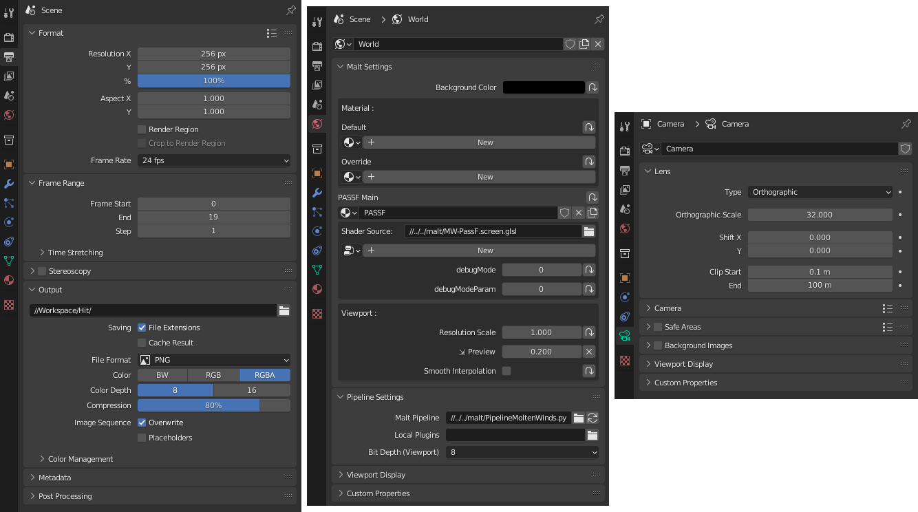
Screenshot of the blender windows for the parameters. Feel free to copy!
Shading and Dithering
Let’s now start the shader proper with the first part: the basic shading. This first pass will do two things: compute the base color, and output additional data for the later passes. We’ll focus now on that first pass.
For this algorithm, I’ll use the simplest of toon shadings: a choice of colors using a threshold. I compute a light coefficient, and if it is above the threshold, I use the lit color, otherwise I use the unlit color.
One modification I’ll do however, is to use an half-lambert shading model. Behind the big name, it just means that instead of doing the regular max(0, normal . light), I do 0.5 * (normal . light) + 0.5. This basically doubles the range I have available with my threshold, and thus can now place the shading terminator even on the shaded half of the model.
A Shading Model is the way we use to compute how light will reflect off of a surface in computer graphics. The one used here is simplistic and basically just says “reflect more light if the light faces the surface”, but it is still very useful for our purposes. I go into more depth in my Toon Shading Fundamentals article!
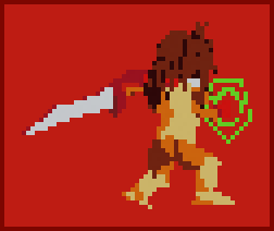
Base two-tone shading on Aster
The control of this is done directly in Malt, thanks to the parameters being exposed automatically. This allows quick and painless changes on each part. Here is the current code.
|
|
This however is not always sufficient, so I’ve added a third tone. It works the exact same, but I didn’t have the need to use it on Aster. Here it is on another character, the Mage of the group.
3-Tone shading on the Mage character. It can give a very “leathery” appearance depending on the colors.
But we still have one last thing to add, once again not present on Aster. The other classic method of shading on models is through dithering, and we’ll add this support with a third character, the Soldier. She needs it for her armor, in order to represent chainmail.
Dithering is a method to represent more colors than possible by putting them in patterns next to each other, and letting the eye mix them for us. It is used in other domains too, but here it is sought after for its aesthetic properties.
The Soldier, without dithering and with dithering. It adds some nice texture!
We could do it in a lot of ways, but I’m going for the simpler one: exact 50% dithering. I’ll do it on the second pass since I already have the pipeline in place. This means I’ll need to add a few parameters, as well as a buffer to store that dithering color. I then compute the pattern using a simple modulo on the sum of the X and Y position, and this part is done!
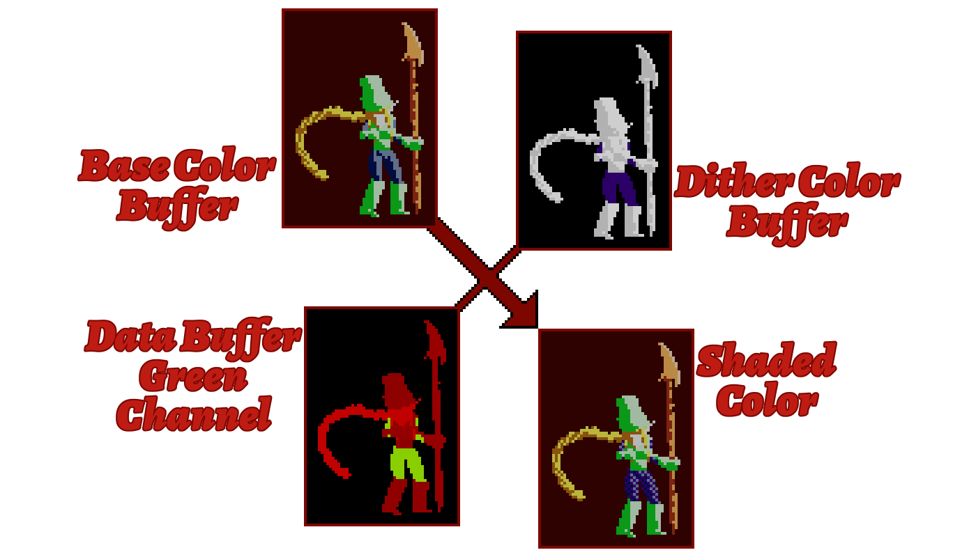
Visual representation of the dithering process and buffers
|
|
Line Rendering
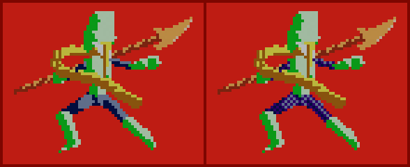
This is the key part of the algorithm, that makes it go from “oh that’s a 3D render” to “how is that 3D!?”. This will be a more complex part, but look for yourself!
Look at the difference! I always find the reaction of people funny when you tell them it’s 3D rendering.
If you’re interested by a deeper dive into this subject, please check out my Line Rendering Overview article! It goes over some of the methods used here.
Line Detection
The first step will be to detect the outline. We will start simple by finding the outside contour, using a screen space extraction method: we’ll find which pixels are outside the character, and next to pixels inside the character. This will give us a simple outline, that we can color black.
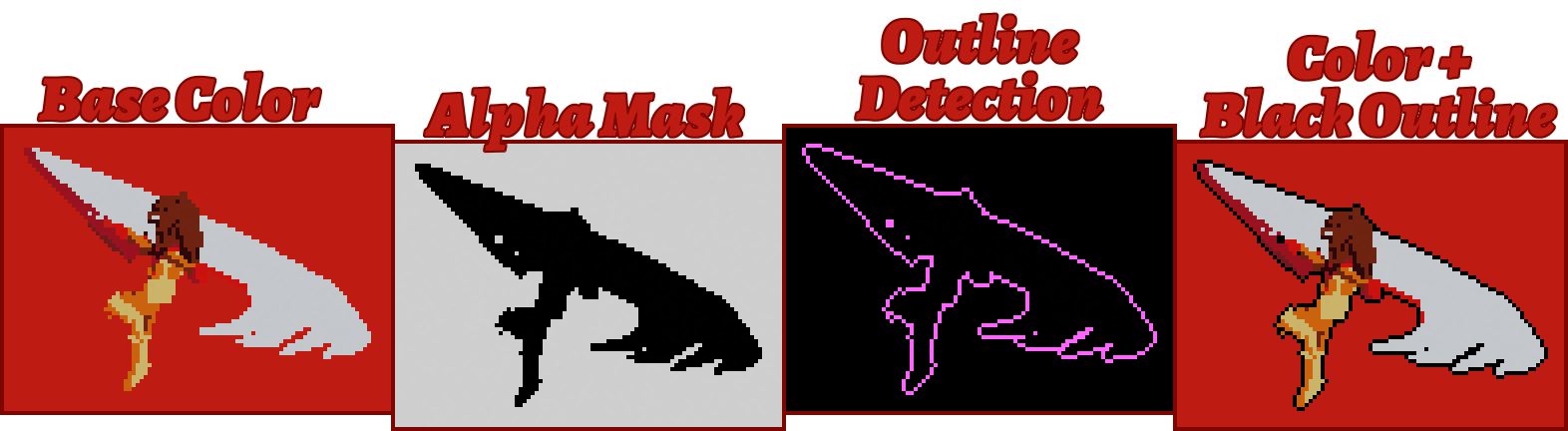
Representation of the algorithm. Note that the two buffers in the middle aren’t stored, it’s just a representation made for this article!
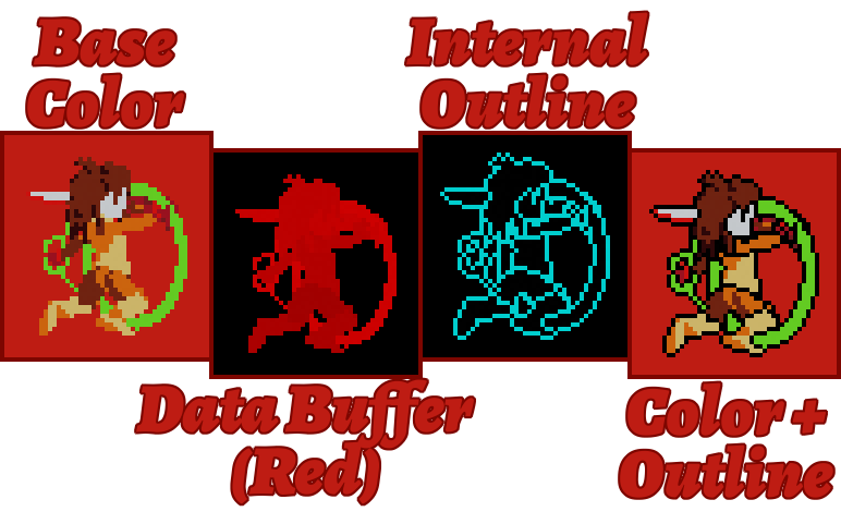
This is a start, however we are very limited here. We will need to clear up the silhouette inside the character too. There are several methods, but I’ve elected for an ID based one for the additional control it offers. This means we’ll need to add a new parameter and buffer, the data buffer (the same one we stored the dithering parameter in).
The main idea is to manually specify which parts are linked together. I do that by specifying a parameter called borderZone. All pixels with the same value will be grouped together for the outline, meaning we will draw the line where those islands meet. This is the result:
Detecting lines using a manual separation provides fairly good results already!
One specificity is however hidden in that algorithm: the lines we drew are one pixel wide exactly. This is significant, because regular convolution methods will produce 2px wide lines. I avoid it by treating borderZone also as a priority: the line will get drawn on the lower priority one.
This can really change the result, as shown in the picture below, but it also helps to hide some of the imperfections of 3D rendering such as some stray pixels.
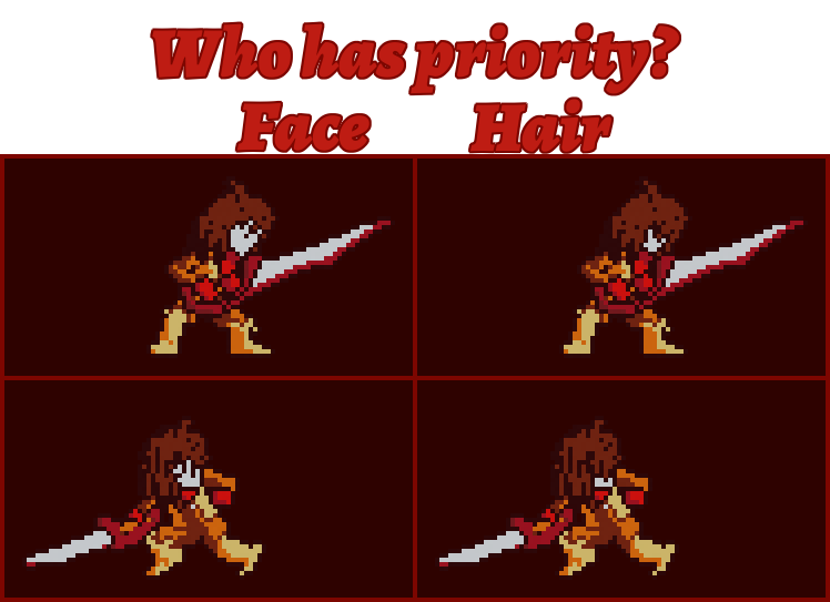
This looks like a shitpost.
Here is the convolution code for reference:
|
|
Line Stylization
Alright, we found the line, but it doesn’t mean it looks good yet. We’ll need to change the line, otherwise we can get some unconvincing results, especially on effects.
The simple solution? Add a line color through a buffer. Let’s look at the result:
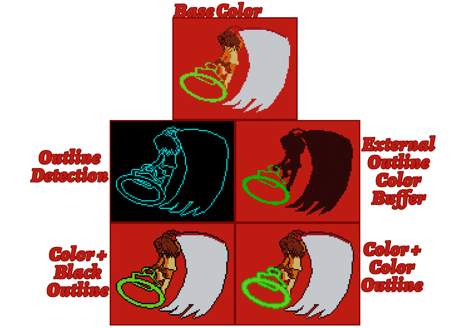
Representation of the buffers for that render. The magic circle looks a lot more right with a lighter color.
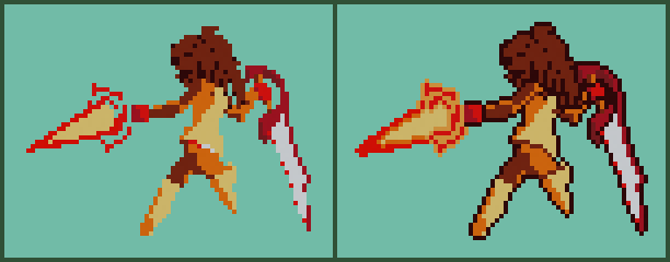
We can go further however. Oftentimes we want to use softer borders inside of the mesh. We’ll use our detection once again to separate outside lines and inside lines, and draw them different colors.
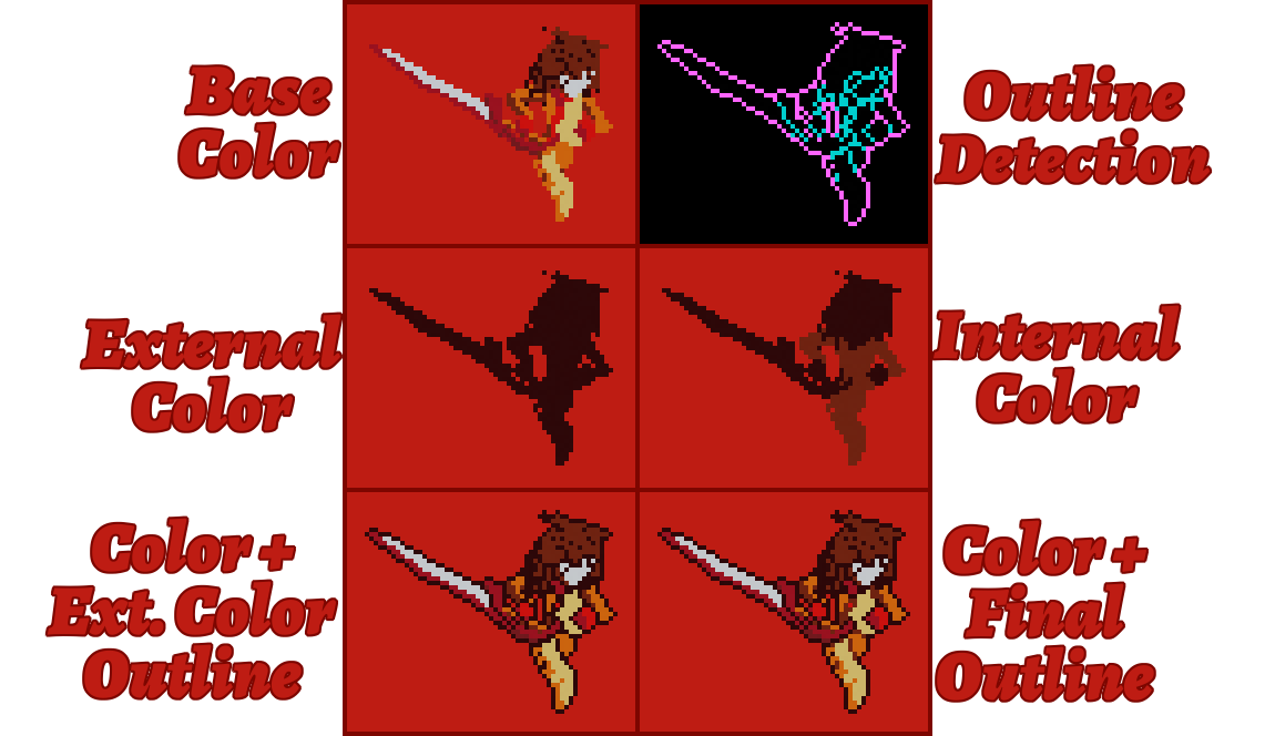
The viewer’s intention is directed a lot better with those new lines, making the sprite more appealing.
And that’s going to be enough for now! The results work fairly well, and the shader based pipeline means we can improve them later fairly easily later. I like the current results quite a bit!
|
|
Making fitting models and animations
To really sell the style, the model needs to be able to mimic some of the limitations. This is why my meshes don’t connect limbs to the core, so that I can move them as if they were separate parts. This type of animation is pretty common since the sprites were already separated into parts, and this setup can help us reproduce it.
I complete that by making animations pose by pose, and trying to retain silhouettes or parts of silhouettes from one frame to the other. Sprites were often reused then, and even if I could render everything at a smooth interpolated 60FPS, it will look very wrong very fast.
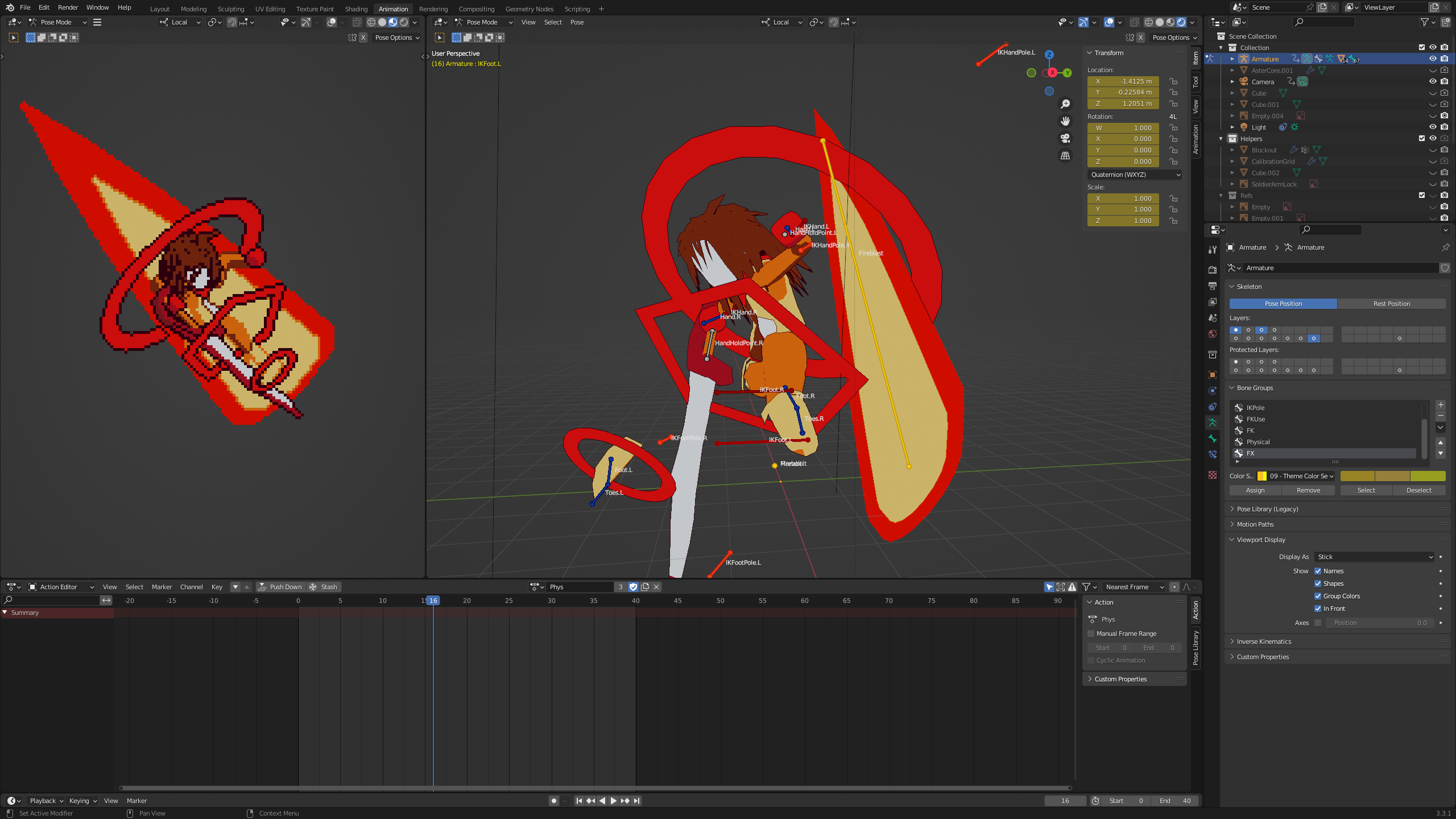
Here’s an example of use using Aster’s Despair Attack. You can see how I’m using the orthographic perspective and model by parts to achieve the look I want!
Exporting as spritesheets
Finally, I want to export those frames to Godot. I have two parts to this trick:
The first part is from the Blender setup: I set my export to a specific folder, and use the fact that each frame is an individual sprite. I then load the animation I want, press Ctrl+F12 and bam! I got all the images I need through Blender’s regular process.
The second part is putting them in spritesheets, which I do using a simple python script with Pillow. It’s a fairly simple script that’ll just add the frames one after another. There are then ready to be used by Castagne!
Conclusion
And there you have it, a complete pipeline to render GBC style sprites! There’s of course a few limitations with its current form, that I may or may not address:
- Editor preview is a bit off and could benefit from being exactly matching the final render size to get more authoring power. This could be solved somewhat easily.
- Zone overlap can be a bit awkward, by having objects in the background show above others, which is only desirable in some cases. This one will require thinking.
- Palette management. While I can do the renders again with other materials (current method), it is fairly time consuming and error prone, so I’ll make a simple color replacement script later on.
- Aesthetic concerns: Some parts of this still betray the 3D origin, and the actual pixel work can be done better by a person. Some heuristics could help, but are probably way too complex for this task.
Here’s a recap of the pipeline itself as a schema!
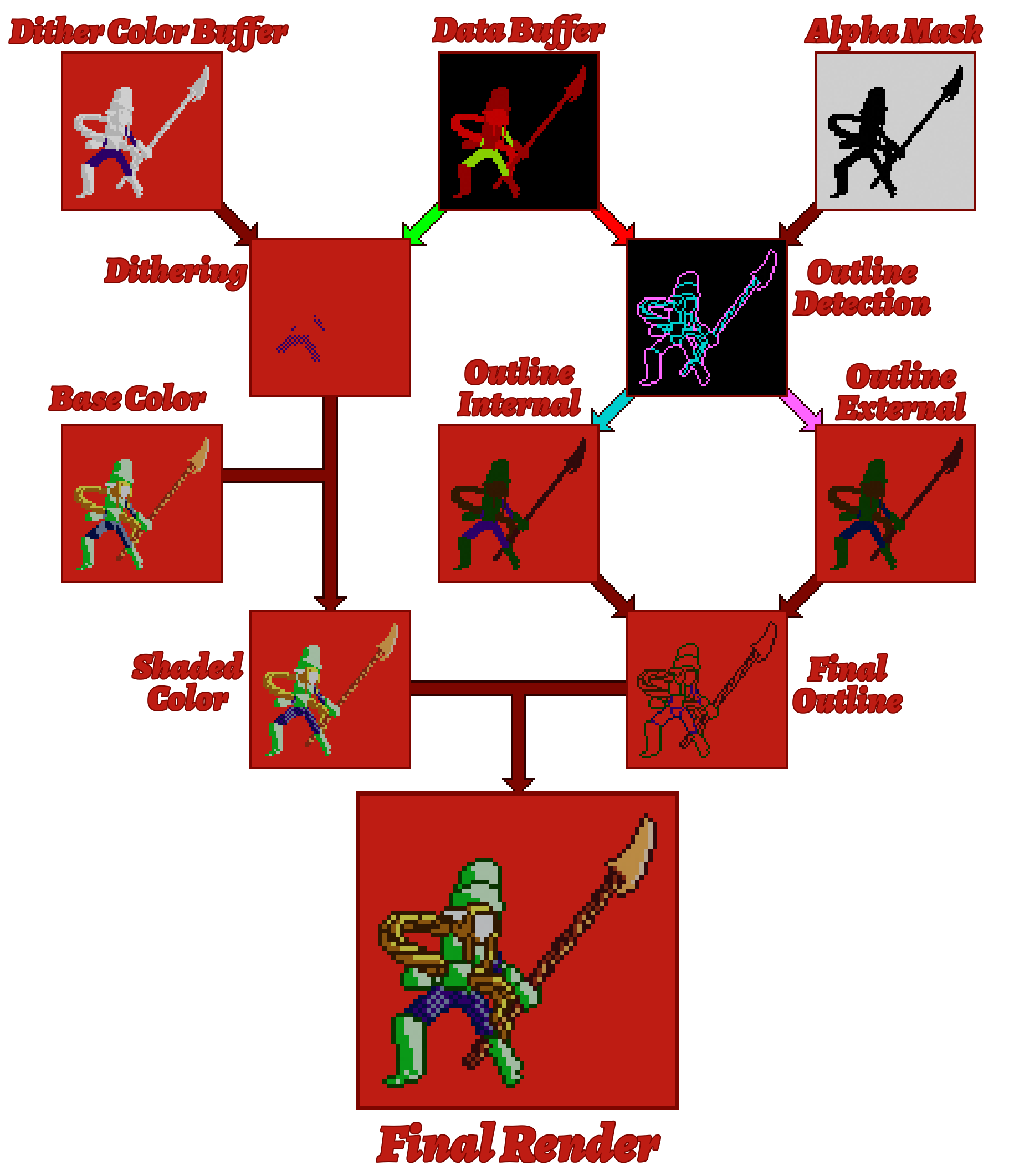
Full representation of the pipeline! It’s simpler in code I think lol
In any case, I’m pretty satisfied with this pipeline! It allows me to make a pretty nice-looking 2D game with minimal effort, with the power of 3D! The pipeline took 2 hours and a half to make, which made this article longer to create! I guess that’s a nice change of pace compared to the usual engine dev life of working for a long time on something that can be summed as “computer go fast”.
That power allows me to make Molten Winds very efficiently, with Aster taking a total of 25h, model, rig, animations, and programming included. This makes character creation more spontaneous compared to Kronian Titans, in which I’m not sure I would even have finished the model in that time. We’ll see how the pipeline evolves with time!
As a side bonus, the algorithm provides a strong, easily understood case for the power of 3D in game creation pipelines. Hopefully this can inspire others to follow in that path! Maybe consider that for your next projects?
Hey! 2025 Panthavma here. I did improve on that whole pipeline here to improve the project beyond its initial, humbler scope. A lot of the concepts explained here still apply, but there’s a lot of subtleties and algorithic improvements that I made that I intend to talk about someday! Subscribe to the newsletter so you don’t miss it!
Updates to the article
2025-10-13: Added some extra links to articles that released, and the extra info on Molten Winds.